Visitors: , Visitors Today: 
Sample Chapter 4:
Painting and Stroking
In this chapter:
Painting
Stroking
Overlap
In the last chapter, we saw how shapes are defined in the 2D API. But what can you do with shapes?
Painting is the process of filling the interior of the shape with a color, color gradient, or texture.
Stroking is the process of drawing the shape's outline. You can draw an outline using different line widths, line styles, and colors.
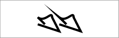
Painting and stroking are very closely related. Stroking, in fact, is just the process of creating a shape that represents an outline and filling it. You can draw outlines using any type of paint. Figure 4-1 shows some examples. On the left, a circle has been filled with a color gradient. In the middle, the same circle's outline is drawn with a thick line using a solid color. On the right, the circle's outline is drawn with the same thick line using the color gradient.
Figure 4-1. Examples of painting and stroking
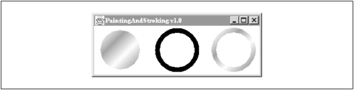
The following class produces the window shown in Figure 4-1. It uses some unfamiliar methods and classes: setPaint(), setStroke(), GradientPaint, and BasicStroke. I'll explain these classes and methods, and more, in the rest of the chapter. For now, this example should show you some of the potential of painting and stroking:
import java.awt.*;
import java.awt.geom.*;
public class PaintingAndStroking
extends ApplicationFrame {
public static void main(String[] args) {
PaintingAndStroking f = new PaintingAndStroking();
f.setTitle("PaintingAndStroking v1.0");
f.setSize(300, 150);
f.center();
f.setVisible(true);
}
public void paint(Graphics g) {
Graphics2D g2 = (Graphics2D)g;
double x = 15, y = 50, w = 70, h = 70;
Ellipse2D e = new Ellipse2D.Double(x, y, w, h);
GradientPaint gp = new GradientPaint(75, 75, Color.white,
95, 95, Color.gray, true);
// Fill with a gradient.
g2.setPaint(gp);
g2.fill(e);
// Stroke with a solid color.
e.setFrame(x + 100, y, w, h);
g2.setPaint(Color.black);
g2.setStroke(new BasicStroke(8));
g2.draw(e);
// Stroke with a gradient.
e.setFrame(x + 200, y, w, h);
g2.setPaint(gp);
g2.draw(e);
}
}
Painting
Filling the interior of a shape is a two-step process:
First, tell the Graphics2D how to fill shapes with a call to setPaint(). This method accepts any object that implements the java.awt.Paint interface. The Graphics2D stores the Paint away as part of its state. When it comes time to fill a shape, Graphics2D will use the Paint to determine what colors should be used to fill the shape. The 2D API comes with three kinds of "canned" paints: solid colors, a linear color gradient, and a texture fill. You can add your own Paint implementations if you wish.
Now you can tell Graphics2D to fill a shape by passing it to fill().
Paints are immutable, which means they can't be modified after they are created. The reason for this is to avoid funky behavior when rendering. Imagine, for example, if you wanted to fill a series of shapes with a solid color. First, you'd call setPaint() on the Graphics2D; then you would paint the shapes using fill(). But what if another part of your program changed the Paint that Graphics2D was using? The results might be quite bizarre. For this reason, objects that implement Paint should not allow themselves to be changed after they are created.
Figure 4-2 shows the three types of painting supported by the 2D API. The figure contains three shapes:
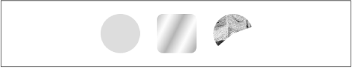
The ellipse is filled with a solid color.
The rounded rectangle is filled with a color gradient.
The arc is filled with a texture, built from van Gogh's Starry Night. Figure 4-2. Three shapes and three paints
Solid Colors
The java.awt.Color class implements the Paint interface. Thus, any Color may be used to fill the interior of a shape. The correct handling of color is a big can of worms--we'll cover it fully in Chapter 8, Color. In the meantime, let's take a quick look at Color. First, the Color class includes some useful colors as static member variables:
public static final Color white;
public static final Color lightGray;
public static final Color gray;
public static final Color darkGray;
public static final Color black;
public static final Color red;
public static final Color pink;
public static final Color orange;
public static final Color yellow;
public static final Color green;
public static final Color magenta;
public static final Color cyan;
public static final Color blue;
If you don't see a color you like, it's easy to create a new color by specifying red, green, and blue values. Colors created in this way are part of a default standard RGB color space called sRGB. We'll talk all about this concept in Chapter 8. You can create new colors using integers or floating point values:
public Color(int r, int g, int b)
This constructor creates a new Color using the specified values for red, green and blue. The values should range from 0 to 255, inclusive.
public Color(float r, float g, float b)
This constructor creates a new Color using the specified values for red, green and blue. The values should range from 0.0 to 1.0, inclusive.
In the following example, a pie-shaped arc is filled with the color blue.
import java.awt.*;
import java.awt.geom.*;
public class SolidPaint
extends ApplicationFrame {
public static void main(String[] args) {
SolidPaint f = new SolidPaint();
f.setTitle("SolidPaint v1.0");
f.setSize(200, 200);
f.center();
f.setVisible(true);
}
public void paint(Graphics g) {
Graphics2D g2 = (Graphics2D)g;
Arc2D pie = new Arc2D.Float(0, 50, 150, 150, -30, 90, Arc2D.PIE);
g2.setPaint(Color.blue);
g2.fill(pie);
}
}
You may remember that setColor(), defined in Graphics, could be used to affect the color of filled shapes. In the 2D API, it is now a convenience method; a call to setColor(c) on a Graphics2D is equivalent to calling setPaint(c).
Swing's Color Chooser Dialog
If you want your users to be able to choose colors in your application, you're in luck. Swing has a ready-made dialog for this purpose. The name of the class is javax.swing.JColorChooser. You can use this dialog with one line of code, using the following static method:
public static Color showDialog(Component component, String title, Color initialColor)
This method displays a color chooser dialog. The supplied Component is used as the parent component of the dialog. The dialog will have the supplied title; its controls will be initialized to show the given initialColor.
The following example demonstrates the use of this dialog. You can invoke the color chooser by pressing the button. After you've made a selection, the background of the frame window changes to the selected color.
import java.awt.*;
import java.awt.event.*;
import javax.swing.*;
public class RedTown
extends JFrame {
public static void main(String[] args) {
new RedTown();
}
public RedTown() {
super("RedTown v1.0");
createUI();
setVisible(true);
}
protected void createUI() {
setSize(400, 400);
setLocation(100, 100);
getContentPane().setLayout(new GridBagLayout());
JButton colorButton = new JButton("Choose a color...");
getContentPane().add(colorButton);
colorButton.addActionListener(new ActionListener() {
public void actionPerformed(ActionEvent ae) {
Color c = JColorChooser.showDialog(
RedTown.this, "Choose a color...", getBackground());
if (c != null) getContentPane().setBackground(c);
}
});
addWindowListener(new WindowAdapter() {
public void windowClosing(WindowEvent we) {
System.exit(0);
}
});
}
}
For more information about the color chooser dialog, see Java Swing, by Robert Eckstein, Marc Loy, and Dave Wood (O'Reilly).
GradientPaint
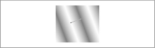
A gradient is a smooth transition from one color to another. In the late evening on a clear day, the sky has a gradient from dark blue at the horizon to black overhead. The 2D API provides an implementation of a simple color gradient, called java.awt.GradientPaint. This class defines a color gradient using two points and two colors. The gradient smoothly shifts from one color to the other as you move along the line that connects the two points, which I'll call the gradient line. The GradientPaint creates parallel bands of color, perpendicular to the gradient line. Figure 4-3 shows a gradient that runs from white to dark gray. The gradient line and its endpoints are also shown.
Figure 4-3. An acyclic linear gradient

Figure 4-4 shows what this looks like.
NOTE:
The appearance of a gradient depends on your screen settings. If your display uses fewer than 24 bits per pixel (bpp), for example, you may see bands of color in gradients, rather than a smooth transition from one color to another.
To create a GradientPaint, you simply need to supply two points and two Colors. By default, GradientPaints are acyclic.
public GradientPaint(Point2D pt1, Color color1, Point2D pt2, Color color2)
public GradientPaint(float x1, float y1, Color color1, float x2, float y2, Color color2)
These constructors create acyclic GradientPaints. The gradient runs from color1 at the first point to color2 at the second point.
public GradientPaint(Point2D pt1, Color color1, Point2D pt2, Color color2, boolean cyclic)
public GradientPaint(float x1, float y1, Color color1, float x2, float y2, Color color2, boolean cyclic)
These constructors create GradientPaints that run from color1 at the first point to color2 at the second point. If the cyclic parameter is true, the gradient will be cyclic.
You can retrieve the parameters of the gradient paint with the following methods:
public Point2D getPoint1()
public Color getColor1()
public Point2D getPoint2()
public Color getColor2()
public boolean isCyclic()
The next example shows how to create a circle and fill it with a cyclic gradient:
import java.awt.*;
import java.awt.geom.*;
public class GradientPaintFill
extends ApplicationFrame {
public static void main(String[] args) {
GradientPaintFill f = new GradientPaintFill();
f.setTitle("GradientPaintFill v1.0");
f.setSize(200, 200);
f.center();
f.setVisible(true);
}
public void paint(Graphics g) {
Graphics2D g2 = (Graphics2D)g;
Ellipse2D e = new Ellipse2D.Float(40, 40, 120, 120);
GradientPaint gp = new GradientPaint(75, 75, Color.white,
95, 95, Color.gray, true);
g2.setPaint(gp);
g2.fill(e);
}
}
TexturePaint
The third type of Paint is a texture fill. In the 2D API, a texture is created using an image that is repeated over and over, like a kitchen floor tile. The java.awt.TexturePaint class represents a texture. You can construct a TexturePaint with two pieces of information:
The image to be used should be supplied as a BufferedImage. I'll talk about images in detail in Chapter 9, Images For now, just think of a BufferedImage as a rectangular picture.
A Rectangle2D specifies how the image will be replicated to form the texture. I'll call this the texture rectangle.
The image is scaled to fit in the given rectangle. This rectangle is reproduced like a floor tile to build the texture. Figure 4-5 shows a TexturePaint and its texture rectangle. Note that the image is drawn to exactly fill the texture rectangle.
Figure 4-5. A texture fill
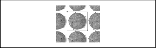
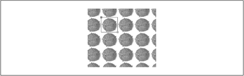
Figure 4-6. A texture with a small texture rectangle
Creating a TexturePaint is as simple as specifying an image and a rectangle:
public TexturePaint(BufferedImage txtr, Rectangle2D anchor)
This constructor creates a TexturedImage that replicates the supplied image using the anchor rectangle.
You can retrieve the image and the rectangle of a TexturePaint with the following methods:
public BufferedImage getImage()
public Rectangle2D getAnchorRect()
The following example shows how to create a TexturePaint from a JPEG image file. The constructor takes care of these details, which I'll describe fully in Chapter 9. In the paint() method, the image is used to create a TexturePaint. Then the texture is used to fill a rounded rectangle.
import java.awt.*;
import java.awt.geom.*;
import java.awt.image.BufferedImage;
import java.io.*;
import com.sun.image.codec.jpeg.*;
public class TexturePaintFill
extends ApplicationFrame {
public static void main(String[] args) throws Exception {
TexturePaintFill f = new TexturePaintFill("roa2.jpg");
f.setTitle("TexturePaintFill v1.0");
f.setSize(200, 200);
f.center();
f.setVisible(true);
}
private BufferedImage mImage;
public TexturePaintFill(String filename)
throws IOException, ImageFormatException {
// Load the specified JPEG file.
InputStream in = getClass().getResourceAsStream(filename);
JPEGImageDecoder decoder = JPEGCodec.createJPEGDecoder(in);
mImage = decoder.decodeAsBufferedImage();
in.close();
}
public void paint(Graphics g) {
Graphics2D g2 = (Graphics2D)g;
// Create a round rectangle.
RoundRectangle2D r =
new RoundRectangle2D.Float(25, 35, 150, 150, 25, 25);
// Create a texture rectangle the same size as the texture image.
Rectangle2D tr = new Rectangle2D.Double(0, 0,
mImage.getWidth(), mImage.getHeight());
// Create the TexturePaint.
TexturePaint tp = new TexturePaint(mImage, tr);
// Now fill the round rectangle.
g2.setPaint(tp);
g2.fill(r);
}
}
Under the Hood
How does the Paint interface really work? Every Paint object has an associated context, a java.awt.PaintContext, which knows what colors to put on a drawing surface. When Graphics2D needs to fill a shape, it asks its current Paint for the corresponding PaintContext. Then it uses the PaintContext to actually put color on the drawing surface.
The Transparency interface
Paint is a subinterface of java.awt.Transparency, an interface which describes an object's use of alpha. It describes three modes, represented by constants:
public static final int OPAQUE
This constant represents objects whose pixels are all opaque (alpha is 1.0 everywhere).
public static final int BITMASK
This constant represents objects whose pixels are either opaque or completely transparent (alpha is 1.0 or 0.0).
public static final int TRANSLUCENT
This constant is used for objects whose pixels may have any values of alpha.
The Transparency interface has only one method:
public int getTransparency()
This method returns the transparency mode, either OPAQUE, BITMASK, or TRANSLUCENT.
The Transparency interface is implemented by the ColorModel class, which is related to images and drawing surfaces (see Chapter 11, Image Guts).
The Paint interface
As I mentioned, Transparency is the parent interface of Paint. The Paint interface itself has only one method--it just knows how to generate a PaintContext:
public PaintContext createContext(ColorModel cm, Rectangle deviceBounds, Rectangle2D userBounds, AffineTransform xform, RenderingHints hints)
This method is called to create a PaintContext. The PaintContext is encouraged to produce colors in the given color model (see Chapter 11). The deviceBounds rectangle indicates the bounds of the drawing surface, while userBounds indicates the bounds of the shape that is being filled. The supplied AffineTransform (see Chapter 5, Rendering) indicates the transformation currently in effect, while hints contains information that the PaintContext can use to modify its behavior. The TexturePaint context, for example, is responsive to the KEY_INTERPOLATION hint. See Chapter 5 for an explanation of rendering hints.
Simple Paint implementations can ignore a lot of the parameters that are passed to createContext(), as you'll see in an upcoming example.
The PaintContext interface
The PaintContext returned by createContext() knows how to actually generate the colors of the Paint. The PaintContext interface defines three methods:
public void dispose()
This method is called when the PaintContext is no longer needed. If you've allocated any images or other large objects, you can free up their references in this method.
public ColorModel getColorModel()
This method returns the color model that will be used for this context's output. This could be a different color model than the one suggested in the createContext() method, back in the Paint interface.
public Raster getRaster(int x, int y, int w, int h)
This is the mother lode of the PaintContext interface. This method returns a Raster that contains the color data that should be used to fill a shape. (The Raster class is part of 2D's image classes. See Chapter 11.)
There's a lot of material here that I won't cover until later chapters. But to show you how simple a Paint can be, I'll present a custom implementation of the Paint interface.
A radial color gradient
The goal of this example is to create a round, or radial, gradient. This gradient defines a color at a point; the gradient blends into another color as a function of the distance from that point. The end result is a big, fuzzy spot. Figure C-2 shows a round rectangle that is filled with the radial gradient.
The implementation consists of two classes, RoundGradientPaint and RoundGradientContext. RoundGradientPaint doesn't do much except return a RoundGradientPaintContext from its createContext() method. Round-GradientPaint's constructor accepts a point and a color that describe the center of the gradient, a radius, and a background color. The gradient blends color from the center point to the background color over the length of the radius.
import java.awt.*;
import java.awt.geom.*;
import java.awt.image.ColorModel;
public class RoundGradientPaint
implements Paint {
protected Point2D mPoint;
protected Point2D mRadius;
protected Color mPointColor, mBackgroundColor;
public RoundGradientPaint(double x, double y, Color pointColor,
Point2D radius, Color backgroundColor) {
if (radius.distance(0, 0) <= 0)
throw new IllegalArgumentException("Radius must be greater than 0.");
mPoint = new Point2D.Double(x, y);
mPointColor = pointColor;
mRadius = radius;
mBackgroundColor = backgroundColor;
}
public PaintContext createContext(ColorModel cm,
Rectangle deviceBounds, Rectangle2D userBounds,
AffineTransform xform, RenderingHints hints) {
Point2D transformedPoint = xform.transform(mPoint, null);
Point2D transformedRadius = xform.deltaTransform(mRadius, null);
return new RoundGradientContext(transformedPoint, mPointColor,
transformedRadius, mBackgroundColor);
}
public int getTransparency() {
int a1 = mPointColor.getAlpha();
int a2 = mBackgroundColor.getAlpha();
return (((a1 & a2) == 0xff) ? OPAQUE : TRANSLUCENT);
}
}
The getTransparency() method, from the Transparency interface, returns either OPAQUE or TRANSLUCENT, depending on the colors that were passed to RoundGradientPaint's constructor. If both colors are fully opaque (alpha = 255), then the resulting RoundGradientPaint is also fully opaque. Otherwise, the pixels filled by the RoundGradientPaint will have variable transparency, indicated by the TRANSLUCENT value.
Instead of creating a RoundGradientPaint that uses two opaque colors, you could also achieve an interesting effect using a single color. Consider what would happen if you used new Color(255, 0, 0, 255) as the point color, and new Color(255, 0, 0, 0) as the background color. The gradient would fade from opaque red at the point to a completely transparent red in the background.
The implementation of RoundGradientContext is straightforward. The get-Raster() method iterates over each point in the requested rectangle, calculating the distance from the center point. It calculates a weighting factor, from 0.0 to 1.0, based on the ratio of this distance and the radius.
for (int j = 0; j < h; j++) {
for (int i = 0; i < w; i++) {
double distance = mPoint.distance(x + i, y + j);
double radius = mRadius.distance(0, 0);
double ratio = distance / radius;
if (ratio > 1.0)
ratio = 1.0;
Then it simply uses the weighting factor to linearly interpolate between the center color and the background color:
data[base + 0] = (int)(mC1.getRed() + ratio *
(mC2.getRed() - mC1.getRed()));
data[base + 1] = (int)(mC1.getGreen() + ratio *
(mC2.getGreen() - mC1.getGreen()));
data[base + 2] = (int)(mC1.getBlue() + ratio *
(mC2.getBlue() - mC1.getBlue()));
data[base + 3] = (int)(mC1.getAlpha() + ratio *
(mC2.getAlpha() - mC1.getAlpha()));
Here's the entire class:
import java.awt.*;
import java.awt.geom.*;
import java.awt.image.*;
public class RoundGradientContext
implements PaintContext {
protected Point2D mPoint;
protected Point2D mRadius;
protected Color mC1, mC2;
public RoundGradientContext(Point2D p, Color c1, Point2D r, Color c2) {
mPoint = p;
mC1 = c1;
mRadius = r;
mC2 = c2;
}
public void dispose() {}
public ColorModel getColorModel() { return ColorModel.getRGBdefault(); }
public Raster getRaster(int x, int y, int w, int h) {
WritableRaster raster =
getColorModel().createCompatibleWritableRaster(w, h);
int[] data = new int[w * h * 4];
for (int j = 0; j < h; j++) {
for (int i = 0; i < w; i++) {
double distance = mPoint.distance(x + i, y + j);
double radius = mRadius.distance(0, 0);
double ratio = distance / radius;
if (ratio > 1.0)
ratio = 1.0;
int base = (j * w + i) * 4;
data[base + 0] = (int)(mC1.getRed() + ratio *
(mC2.getRed() - mC1.getRed()));
data[base + 1] = (int)(mC1.getGreen() + ratio *
(mC2.getGreen() - mC1.getGreen()));
data[base + 2] = (int)(mC1.getBlue() + ratio *
(mC2.getBlue() - mC1.getBlue()));
data[base + 3] = (int)(mC1.getAlpha() + ratio *
(mC2.getAlpha() - mC1.getAlpha()));
}
}
raster.setPixels(0, 0, w, h, data);
return raster;
}
}
And here's a simple class that demonstrates how you can use Round-GradientPaint to fill a round rectangle:
import java.awt.*;
import java.awt.geom.*;
public class RoundGradientPaintFill
extends ApplicationFrame {
public static void main(String[] args) {
RoundGradientPaintFill f = new RoundGradientPaintFill();
f.setTitle("RoundGradientPaintFill v1.0");
f.setSize(200, 200);
f.center();
f.setVisible(true);
}
public void paint(Graphics g) {
Graphics2D g2 = (Graphics2D)g;
RoundRectangle2D r = new RoundRectangle2D.Float(25, 35, 150, 150, 25,
25);
RoundGradientPaint rgp = new RoundGradientPaint(75, 75, Color.magenta,
new Point2D.Double(0, 85), Color.blue);
g2.setPaint(rgp);
g2.fill(r);
}
}
When you run this example, you should see the window shown in Figure C-2.
Stroking
Stroking is the process of drawing the outline of a shape. Stroking is similar to painting:
First, tell the Graphics2D how you want the outline to be drawn by calling setStroke(). This method accepts any object that implements the java.awt.Stroke interface. The 2D API comes with a class, java.awt.BasicStroke, that implements common stroking options.
Use setPaint() to tell the Graphics2D how the outline itself should be drawn. Outlines, like the interior of shapes, can be drawn using a color, a gradient, a texture, or anything else that implements the Paint interface.
Draw the outline of the shape using Graphics2D's draw() method. The Graphics2D uses the Stroke from step 1 to determine what the outline looks like. The Paint from step 2 is used to actually render the outline.
Stroke
Graphics2D uses a Stroke to figure out what the outline of a particular shape looks like. When you ask Graphics2D to draw() a shape, it asks its Stroke what the outline of the shape should look like. Interestingly, Stroke returns the stroked outline as another shape:
public abstract Shape createStrokedShape(Shape p)
This method returns a Shape that represents the stroked outline of the supplied shape.
This is the only method in Stroke. Usually, you won't call it yourself--a Graphics2D will call it on your behalf when you draw() a shape.
At first glance, it seems strange that the outline of a Shape is also a Shape. It may help to think of the outline of a Shape as an infinitesimally thin line--to actually draw the outline, you need to give it some area, which is the process of stroking. Once you have the stroked outline, you can fill it in to draw the original shape's outline. In fact, calling draw() on a Graphics2D is equivalent to the following code:
public void longwindedDraw(Graphics2D g2, Shape s) {
Stroke stroke = g2.getStroke();
Shape strokedOutline = stroke.createStrokedShape(s);
g2.fill(strokedOutline);
}
BasicStroke
The 2D API comes with a Stroke implementation called java.awt.BasicStroke. This class supports solid and dashed lines of any width. BasicStroke also handles two details of drawing thick lines: end styles and join styles.
End styles
There are several ways to draw the end of a thick line. BasicStroke supports three styles, represented by constants. Figure 4-7 shows an example of each end style.
Figure 4-7. End styles
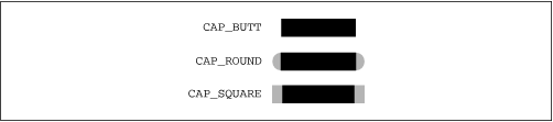
public static final int CAP_BUTT
This end style adds no decoration to the end of line segments. Straight line segments stroked using this end style appear as rectangles.
public static final int CAP_ROUND
This end style caps a line segment with a semicircle whose radius is half the line width.
public static final int CAP_SQUARE
This end style extends the end of the line with a rectangle whose length is half the line width.
Note that these end styles apply to the ends of any line segment, straight or curved.
Join styles
BasicStroke offers three different ways to join line segments. Again, these join styles are represented by constants in BasicStroke. Figure 4-8 shows how the different join styles work. Figure 4-9 shows an example of each join style.
Figure 4-8. Join styles
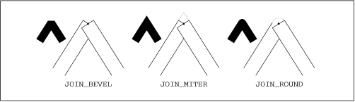
public static final int JOIN_BEVEL
Lines are joined by connecting the outer edges of their ends.
public static final int JOIN_MITER
In this join style, the outer edges of lines are extended until they intersect. If the miter is longer than a supplied miter limit, however, the join will be rendered as a beveled join.
public static final int JOIN_ROUND
Each line segment is ended with a semicircle, as in the CAP_ROUND end style. This creates a rounded effect at the intersection of line segments.
The miter limit used with JOIN_MITER does not correspond directly to the length of the miter. The algorithm depends on three quantities:
halfLength
This is half of the line width.
miterLength
The length of the miter is measured from the intersection of the two (unstroked) lines to the tip of the miter.
miterLimit
This is the miter limit as specified in the BasicStroke constructor.
If miterLength is greater than (miterLimit * halfWidth), a beveled join will be used instead of a mitered join. Otherwise, a mitered join is used. The purpose of the miter limit is to prevent awkward-looking miter joins from being drawn. If two lines are nearly parallel, a mitered join will extend far beyond the actual intersection of the lines. Figure 4-10 illustrates this effect. In it, the same shape is stroked with a miter limit of 10.0 and 25.0.
Figure 4-10. Mitered joins can be unruly
Dashes
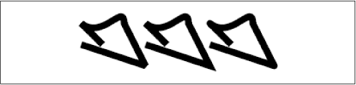
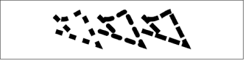
BasicStroke uses a dash array and a dash phase to stroke dashed lines. The dash array is an array of floats that represent the length of the solid and clear sections of the line. For example, an array consisting of { 12, 12 } would produce a line that was visible for 12 units and invisible for 12 units. The even elements of the array (starting at index 0) determine where the line is visible, while the odd elements determine where it's invisible. Figure 4-11 shows a GeneralPath stroked with two varieties of dotted lines. The shape on the left has been stroked with a solid line. In the middle, the shape has been stroked using a dash array of { 12, 12 }. The same shape is stroked again on the right, using a dash array of { 4, 4, 12, 4 }.
Figure 4-11. Stroking dashed lines

The end style is used on each dash in a dashed line. Figure 4-12 shows the same dashed line drawn using the CAP_BUTT, CAP_ROUND, and CAP_SQUARE end styles.
Figure 4-12. End styles apply to dashes, too
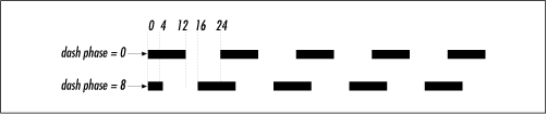
The dash phase acts as an offset into the dash pattern. Consider, for example, the dash array { 12, 12 }. When the dash phase is 0, lines stroked with this dash pattern will begin with 12 units of visible outline followed by 12 units that are invisible. Suppose, instead, that the dash phase is set to 8. Now, lines stroked with the dash pattern will begin with 4 units of visible line, followed by 12 units of invisible, followed by 12 of visible, and so forth. Figure 4-13 shows how this works for two straight lines.
Figure 4-13. Same dashes, different dash phases
Constructors
Once you understand the end styles, join styles, and dashes, it's easy to create a BasicStroke that does exactly what you want it to do. Like Paint objects, Strokes cannot be changed after they have been constructed.
public BasicStroke()
This constructor creates a stroke object with all the default settings: a solid stroke with a line width of 1.0, an end style of CAP_SQUARE, a join style of JOIN_MITER, a miter limit of 10.0.
public BasicStroke(float width)
This constructor creates a stroke object with the supplied width. The other settings are set to their defaults, as described in the previous constructor.
public BasicStroke(float width, int cap, int join)
This constructor creates a solid stroke object with the given width, end style, and join style. If the join style is JOIN_MITER, the default miter limit of 10.0 is used.
public BasicStroke(float width, int cap, int join, float miterlimit)
This constructor is the same as the previous constructor, except that the given miter limit will be used if the join style is JOIN_MITER.
public BasicStroke(float width, int cap, int join, float miterlimit, float[] dash,
float dash_phase)
This constructor creates a dashed stroke object. The supplied dash array and phase are used to determine the dashing pattern.
The following example creates a square and strokes it:
Rectangle2D r = new Rectangle2D.Double(50, 50, 100, 100);
Stroke stroke = new BasicStroke(8,
BasicStroke.CAP_BUTT, BasicStroke.JOIN_BEVEL, 0,
new float[] { 12, 12 }, 0);
g2.setStroke(stroke);
g2.draw(r);
Overlap
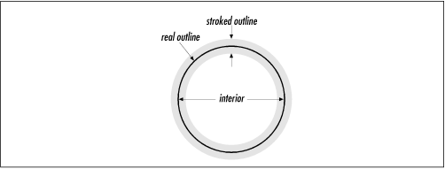
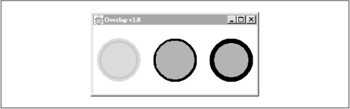
What happens if you both stroke and paint a shape? Interestingly, the results depend on whether you stroke or paint first. A shape's outline actually overlaps its interior, as shown in Figure 4-14. The shape's real outline, strictly speaking, is an infinitesimally thin line, shown black in the figure. The process of stroking creates an outline shape around the real outline. Some of the stroked outline extends outside the shape, and some of the stroked outline overlaps with the shape's interior.
Figure 4-14. The stroked outline and interior of a circle
If you're using opaque colors, then you'll get different results depending on the order in which you do things. If you use partially transparent colors, then you'll be able to observe the overlap of stroked outlines and filled interiors in your results. The following shows how this happens in practice. First, it strokes the outline and fills the interior of a circle using a partially transparent color:
Color smokey = new Color(128, 128, 128, 128);
g2.setPaint(smokey);
g2.fill(e);
g2.draw(e);
Then, in a different location, it strokes the circle's outline using a solid black color and fills the interior using a solid gray:
g2.setPaint(Color.black);
g2.draw(e);
g2.setPaint(Color.gray);
g2.fill(e);
Finally, it fills the circle with gray and then strokes the outline with black:
g2.setPaint(Color.gray);
g2.fill(e);
g2.setPaint(Color.black);
g2.draw(e);
The results of this example are shown in Figure 4-15.
Figure 4-15. Stroking and painting overlap
Here's the source code:
import java.awt.*;
import java.awt.geom.*;
public class Overlap
extends ApplicationFrame {
public static void main(String[] args) {
Overlap f = new Overlap();
f.setTitle("Overlap v1.0");
f.setSize(300, 150);
f.center();
f.setVisible(true);
}
public void paint(Graphics g) {
Graphics2D g2 = (Graphics2D)g;
double x = 15, y = 50, w = 70, h = 70;
Ellipse2D e = new Ellipse2D.Double(x, y, w, h);
g2.setStroke(new BasicStroke(8));
// Stroke and paint.
Color smokey = new Color(128, 128, 128, 128);
g2.setPaint(smokey);
g2.fill(e);
g2.draw(e);
// Stroke, then paint.
e.setFrame(x + 100, y, w, h);
g2.setPaint(Color.black);
g2.draw(e);
g2.setPaint(Color.gray);
g2.fill(e);
// Paint, then stroke.
e.setFrame(x + 200, y, w, h);
g2.setPaint(Color.gray);
g2.fill(e);
g2.setPaint(Color.black);
g2.draw(e);
}
}
Copyright © 2011 - All Rights Reserved - Softron.in
Template by Softron Technology